| Home | Description | Geometry and Conditions | Instructions to participants |

Case 3.12

Conditions:

\( {R_{e}}^{*}\) : nominal Reynolds number, the Reynolds number when ship runs in calm water with constant propeller rate of revolution.
\( {F_r}^{*}\) : nominal Froude number, the Froude number when ship runs in calm water with constant propeller rate of revolution.
\(\lambda\) : wave length
\(H\) : wave height
\(\zeta_a\) : wave amplitude, \(\zeta_a = \displaystyle{\frac{H}{2}}\)
\(k\) : wave number, \(\displaystyle{k=\frac{2 \pi}{\lambda}}\)

All quantities are non-dimensionalized by approach speed (\(V_A\)), and waterline length (\(L_{WL}\)): \begin{align*} {F_r}^{*} = \frac{V_A}{\sqrt{g \cdot L_{WL}}}, \quad {R_e}^{*} = \frac{V_A\ \cdot L_{WL}}{\nu} \tag{1} \end{align*} where \(g\) is the gravitational acceleration and \(\nu\) is the kinematic viscosity.

Computational Setup:

  1. All calculations are to be conducted for model scale conditions.
  2. All simulations results should be provided in the format described in next section.
  3. Constant rate of revolution \(n\) should be applied throughout the simulation. \(n\) should correspond to the self propulsion point of the model (In case self-propulsion cannot be carried out, \(n\) should be set the measured value 8.97[rps]).
  4. Similar to the experiment, the rudders should be controlled by following autopilot: \begin{align*} \delta (t) = K_P ( \psi (t) - \psi_C ) \tag{2} \end{align*} where \(\delta (t)\) is rudder angle, proportional gain \( K_P \) is 1.0, \(\psi_C\) is the target yaw angle and \(\psi (t)\) is yaw angle. The maximum rudder rate should be assigned to \(35.0\) [deg/s].
  5. Mimicking the experimental data, the ship should be located initially at the target yaw angle \(\psi_C\) and then towed until the propeller rate of revolution and ship speed are at the desired value. After the desired \(n\) and ship speed are achieved, the ship should be released when the wave crest is located at the bow.
  6. If the experimental procedure for releasing the ship cannot be carried out, the model can be released with the initial yaw motion of \(\psi_C\), speed corresponding to \({F_r}^{*}=0.2\) and propellers operating at self-propulsion point. The wave crest should be located at the bow when the ship is released following the experimental setup.

General Format for Submissions:

  1. The trajectory \(\displaystyle{\left(\frac{X-X_0}{L_{WL}}, \frac{Y-Y_0}{L_{WL}}\right)}\) and time histories of heave \(\displaystyle{\frac{Z}{\zeta_a}}\), angular motions \((\displaystyle{\frac{\phi}{k \zeta_a}, \frac{\theta}{k \zeta_a}, \frac{\psi - \psi_C}{k \zeta_a}})\) , velocities for 6DOF motions \((u,v,w,p,q,r)\), rudder angle \(\delta\), thrust coefficient \(K_T\) and torque coefficient \(K_Q\) for each propeller, propeller rate of revolution \(n\) [rps], and wave elevation \(\displaystyle{\frac{\zeta_w}{L_{WL}}}\), after the ship was released (\(t=t_0\)), should be submitted.
  2. The ship position or trajectory should be given in an Earth-fixed coordinate system with \(X\) pointing North, \(Y\) pointing East, and \(Z\) pointing downward as shown in Figure 1. The ship was released at \( (X_0, Y_0)\) when \(t = t_0\) . The roll angle (\(\phi\)) is positive for pushing starboard into the water, pitch (\(\theta\)) is positive for bow up position and yaw angle (\(\psi\)) is positive for bow turned to starboard. The reported trajectory should be normalized by \(L_{WL}\) and angular motions should be reported in degree. The reported yaw angle should be the deviation of yaw angle respect to the target yaw i.e. \(\psi - \psi_C\).
  3. All velocities for 6DOF motions (\(u,v,w,p,q,r\)) should be reported in ship-fixed coordinate system with \(x\) axis positive toward bow, \(y\) axis positive toward starboard and \(z\) axis positive downward. The reported velocities should be non-dimensionalized as: \begin{align*} \left( \begin{array}{c} u \\ v \\ w \end{array} \right) &= \frac{1}{V_A} \left( \begin{array}{c} \dot{x} \\ \dot{y} \\ \dot{w} \end{array} \right) \tag{3} \\ & \\ \left( \begin{array}{c} p \\ q \\ r \end{array} \right) &= \frac{1}{\omega_e k \zeta_a} \left( \begin{array}{c} \dot{\phi} \\ \dot{\theta} \\ \dot{\psi} \end{array} \right) \tag{4} \label{eq:pqr} \end{align*} where \(\omega_e\) is circular wave frequency of encounter defined as \( \omega_e = \sqrt{kg} + k V_A \). In Equation \eqref{eq:pqr}, the unit of \(\dot{\phi}\), \(\dot{\theta}\) and \( \dot{\psi}\) is [rad/s].
  4. Rudder angle (\(\delta\)) is positive when trailing edge moves to starboard.
  5. The thrust \(T\) and torque \(Q\) for each propeller should be reported in shaft coordinate system with \(x\) axis positive toward the engine. Values should be normalized by density of water\(\rho\), propeller diameter (\(D_P\)), and \(n\) as follows. \begin{align*} K_T = \frac{T}{ \rho n^2 {D_P}^4 }, \quad K_Q = \frac{Q}{ \rho n^2 {D_P}^5 } \tag{5} \end{align*}
  6. All motions should be reported at the center of gravity. The wave elevation (\(\zeta_w / L_{WL}\)), which is positive upward, should be reported at \(0.031776 L_{WL}\)(100[mm] in model scale) right from FP at rest.
  7. The time traces for simulations should be shifted such that the release time matches with the one in the measurement reported in Table 3 of EFD procedure.

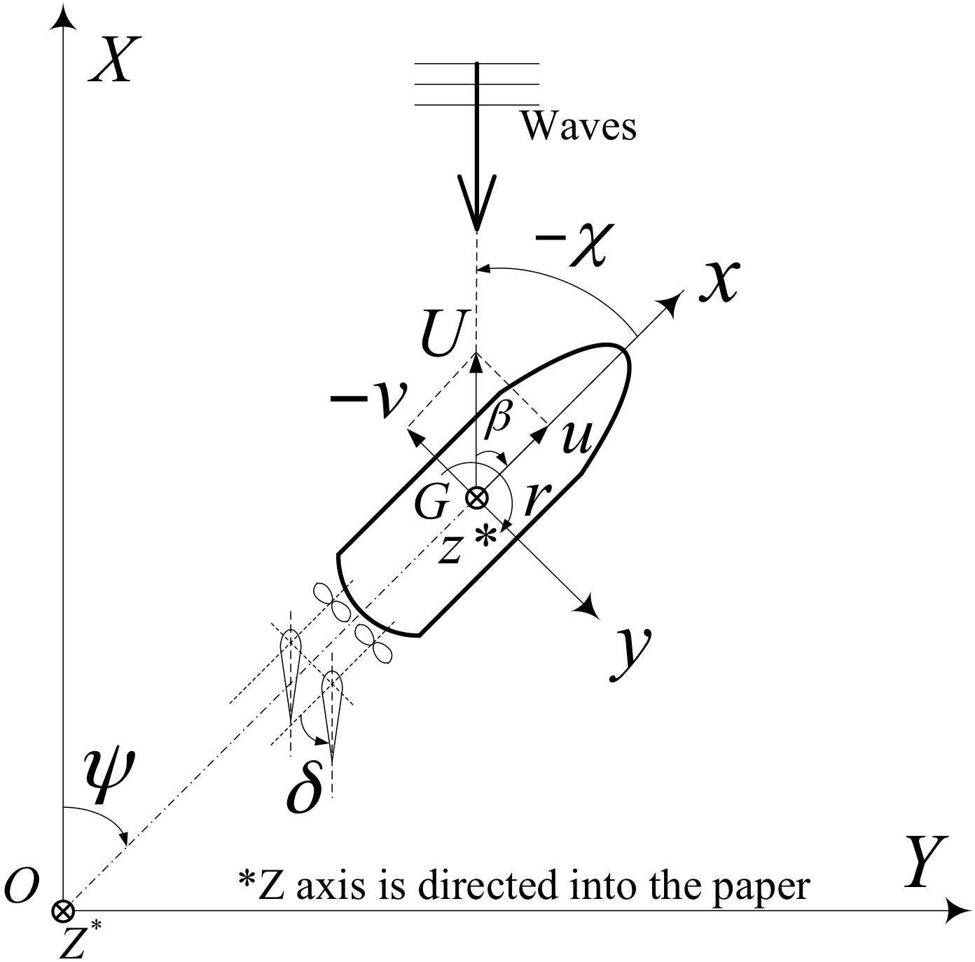
Figure 1: Earth and ship-fixed coordinate system

Submission Instructions:

References:

Not yet available.
Details of EFD procedures are shown here (IIHR_ONRT_DATA_06-12-2015.pdf).

Table/Figure# Items EFD Data Submission Instruction
Data file Image Image files Sample + Tecplot layout file
3.12-1 for \(\psi_C=0^{\circ}\) Trajectory \(\displaystyle{\left(\frac{X-X_0}{L_{WL}}, \frac{Y-Y_0}{L_{WL}}\right)}\)
Time histories of ship motions, rudder angle and wave elevation
\(\displaystyle{\frac{Z}{\zeta_a}}\) \(\displaystyle{\frac{\phi}{k \zeta_a}}\), \(\displaystyle{\frac{\theta}{k \zeta_a}}\), \(\displaystyle{\frac{\psi-\psi_C}{k \zeta_a}}\), \(\displaystyle{u}\), \(\displaystyle{v}\), \(\displaystyle{w}\), \(\displaystyle{p}\), \(\displaystyle{q}\), \(\displaystyle{r}\), \(\displaystyle{\delta}\) and \(\displaystyle{\frac{\zeta_w}{L_{WL}}}\)
Refer to sample file for detail Filename:
[Identifier]_XY_3-12.png ( for Trajectory )
[Identifier]_heave_T-his_3-12.png ( for \(Z/\zeta_a\) )
[Identifier]_roll_T-his_3-12.png ( for \(\phi/(k \zeta_a)\) )
[Identifier]_pitch_T-his_3-12.png ( for \(\theta/(k \zeta_a)\) )
[Identifier]_yawdvtn_T-his_3-12.png ( for \((\psi-\psi_C)/(k \zeta_a)\) )
[Identifier]_u_T-his_3-12.png ( for \(u\) )
[Identifier]_v_T-his_3-12.png ( for \(v\) )
[Identifier]_w_T-his_3-12.png ( for \(w\) )
[Identifier]_p_T-his_3-12.png ( for \(p\) )
[Identifier]_q_T-his_3-12.png ( for \(q\) )
[Identifier]_r_T-his_3-12.png ( for \(r\) )
[Identifier]_rudder_T-his_3-12.png ( for \(\delta\) )
[Identifier]_wave_T-his_3-12.png ( for \(\zeta_w/L_{WL}\) )

X-axis range:
\(\displaystyle{ -0.5 \le \frac{X-X_0}{L_{WL}} \le 9.5 }\) ( for trajectory )
\(\displaystyle{ 0.0 \le \frac{(t-t_0) V_A}{L_{WL}} \le 10.0 }\) ( for time histories )

Y-axis range:
\( \displaystyle{-5.0 \le \frac{Y-Y_0}{L_{WL}} \le 5.0 }\) and positive downward ( for trajectory )
\( \displaystyle{-1.5 \le \frac{Z}{\zeta_a} \le 1.5}\)
\( \displaystyle{-3.0 \le \frac{\phi }{k \zeta_a}\le 3.0}\)
\( \displaystyle{-2.0 \le \frac{\theta }{k \zeta_a}\le 2.0}\)
\( \displaystyle{-2.0 \le \frac{\psi-\psi_C }{k \zeta_a}\le 2.0}\)
\( \displaystyle{0.7 \le u \le 1.2}\)
\( \displaystyle{-0.2 \le v \le 0.2}\)
\( \displaystyle{-0.2 \le w \le 0.2}\)
\( \displaystyle{-1.0 \le p \le 1.0}\)
\( \displaystyle{-1.0 \le q \le 1.0}\)
\( \displaystyle{-1.0 \le r \le 1.0}\)
\( \displaystyle{-10.0 \le \delta \le 10.0}\)
\( \displaystyle{-0.02 \le \frac{\zeta_w}{L_{WL}} \le 0.02}\)

Style:
CFD solid line
EFD open circles

Time interval of EFD data:
\(\Delta t = 0.2 \)[s](4 skips), for trajectory
\(\Delta t = 0.4 \)[s](8 skips), for time histories of \(\phi/(k \zeta_a)\), \((\psi - \psi_C)/(k \zeta_a), p, r\) and \(\delta\)
\(\Delta t = 0.2 \)[s](4 skips), for time histories of \(v\)
\(\Delta t = 0.1 \)[s](2 skips), for time histories of \(u\)
\(\Delta t = 0.05 \)[s], for time histories of the others
Case3.12-000.zip
3.12-2 Time histories of propulsion coefficients
\(K_T\), \(K_Q\) and \(n\)
N/A N/A Filename:
[Identifier]_KT_T-his_3-12.png ( for \(K_T\))
[Identifier]_10KQ_T-his_3-12.png ( for \(10 K_Q\))
[Identifier]_n_T-his_3-12.png ( for \(n\))

X-axis range:
\( \displaystyle{ 0.0 \le \frac{(t-t_0) V_A}{L_{WL}} \le 10.0 }\)

Y-axis range:
\( 0.1 \le K_T \le 0.6\)
\( 0.4 \le 10 K_Q \le 1.2\)
\( 8.0 \le n \le 10.0\)

Style:
Port side solid line
Starboard side dashed line