Hino, T., (2005 ed.), “Proceedings of CFD Workshop Tokyo 2005”, NMRI report 2005
The self propulsion computation is to be carried out at the ship point following the experimental procedure.
Thus, the rate of revolutions of the propeller \(n\) is to be adjusted to obtain force equilibrium in the longitudinal direction considering the applied towing force (Skin Friction Correction, SFC): \(T = R_{T(SP)}-SFC\)
Where \(T\) is the computed thrust, \(R_{T(SP)}\) is the total resistance at self propulsion and SFC = 30.3[N] (from the test).
In case this procedure cannot be carried out, set \(n\) to the measured value \(9.5\)[rps].
| Table/Figure# | Items | EFD Data | Submission Instruction | ||
|---|---|---|---|---|---|
| Data file | Image | Image files | Sample + Tecplot layout file | ||
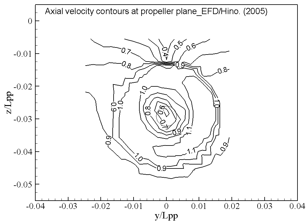
| 2.7-1 | Axial velocity contours and cross flow vectors downstream of propeller plane (\(x/L_{PP}=0.9911\)) |
U_prop_EFD.dat | prop_contour_EFD.jpg prop_contour_EFD.lpk |
Filename: [Identifier]_prop_contour_2-7.jpg Axis: \(-0.04 \le y/L_{PP} \le 0.04 \) \(-0.055 \le z/L_{PP} \le 0.005\) Contours level: \(0 \le u/U \le 1.2\), \(\Delta (u/U) = 0.1\), #levels=13 Line style: solid lines |
Refer to EFD image |
| prop_vector_EFD.jpg prop_vector_EFD.lpk |
Filename: [Identifier]_prop_vector_2-7.jpg Axis: \(-0.04 \le y/L_{PP} \le 0.04 \) \(-0.055 \le z/L_{PP} \le 0.005\) Reference vector: magnitude 0.2 |
Refer to EFD image | |||
| 2.7-2 | Velocity downstream of propeller plane (\(x/L_{PP}=0.9911\)) at \(z/L_{PP}=-0.03\) |
uvw_prop_EFD.dat | Refer to sample file for details |
Filename: [Identifier]_uvw_prop_2-7.jpg Axis: \(-0.03 \le y/L_{PP} \le 0.03\) \(-0.5 \le u/U, v/U, w/U \le 1.2\) Line style: \(u/U\): CFD solid line; EFD open squares \(v/U\): CFD dashed line; EFD open triangles \(w/U\): CFD dotted line; EFD open circles |
[Identifier]_uvw_prop_2-7.jpg |
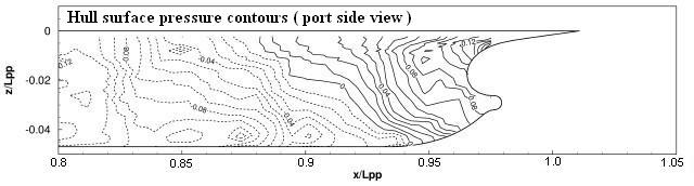
| 2.7-3 | Hull surface pressure contours ( port side view ) |
Not yet available | Cp_port_EFD.jpg |
Filename: [Identifier]_Cp_port_2-7.jpg Axis: \(0.8 \le x/L_{PP} \le 1.05\) \(-0.05 \le z/L_{PP} \le 0.01\) Contours level: \(-1.0 \le C_p \le 1.0\), \(C_p = \frac{p - p_{\infty}}{ \frac{1}{2} \rho U^2}\) \(\Delta C_p=0.01\), #levels=201 Contours style: Solid and dashed lines for positive (+) and negative (-) values, respectively. |
Refer to EFD image |
Note: a positive (+) sinkage value is defined upwards and a positive (+) trim value is defined bow up.
Submission Instructions:
All quantities are non-dimensionalized by denstiy of water (\(\rho\)), ship speed (\(U\)), and length between parpendiculars (\(L_{PP}\)): \begin{align*} F_r = \frac{U}{\sqrt{g \cdot L_{PP}}}, \quad R_e = \frac{U \cdot L_{PP}}{\nu} \end{align*} where \(g\) is the gravitational acceleration and \(\nu\) is the kinematic viscosity.
![[Identifier]_uvw_prop_2-7.jpg]([Identifier]_uvw_prop_2-7.jpg)